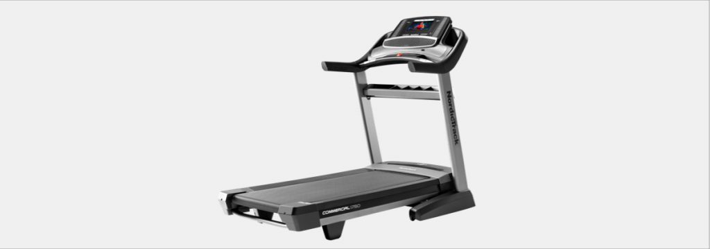
You’ve finally decided to invest in your health by bringing a state-of-the-art machine equipped with interactive personal training right into your home, and we couldn’t feel more honored to be a part of your new healthy lifestyle. With your new NordicTrack Commercial 1750 Treadmill, you are well on your way to living the healthy life you deserve with the workouts that’ll help you every single mile towards success.
Since you’re already aware of all the incredible features of the Commercial 1750––considering your recent purchase––we want to continue to support all of your assembly needs with these set-up instructions.
Commercial 1750 Treadmill Assembly Instructions
- Go to my.nordictrack.com on your computer and register your product. You will be able activate your warranty––saving you time if you ever need to contact Customer Service, and allows us to notify you of upgrades and offers.
Note: If you do not have internet access, call Customer Service (see the front cover of your user’s manual) and register your product. - Make sure that the power cord is unplugged. Remove the tie securing the Upright Wire to the front of the Base. Next, identify the Right Upright. Have a second person hold the Right Upright near the Base. Tie the wire tie in the Right Upright securely around the end of the Upright Wire. Then insert the Upright Wire into the lower end of the Right Upright as you pull the other end of the wire tie through the Right Upright.
- Lay the Right Upright near the Base. Press the Upright Grommet into the square hole in the Right Upright. Make sure not to pinch the ground wire. If there is a screw pre-attached to the Right Upright, remove and discard it. Then attach the ground wire to the Right Upright with a #8 x 1/2″ Silver Screw.
- Hold the Right Upright against the Base. Make sure not to pinch the Upright Wire. Attach the Right Upright with two 3/8″ x 2 3/4″ screws, two 3/8″ x 1 1/4″ screws, and four 3/8″ Star Washers; do not fully tighten the screws yet. Attach the Left Upright in the same way.
Note: There are no wires on the left side. - Identify the Left and Right Base Covers. Slide the Left Base Cover onto the Left Upright, and slide the Right Base Cover onto the Right Upright. Press the Base Covers downward, but do not snap the Base Covers into place yet. Then remove and save the four indicated 5/16″ x 2″ screws. If there is a film covering the decal on each of the Uprights, carefully remove the film.
- Carefully slide the Upright Crossbar between the Right and Left Uprights. Attach the Upright Crossbar with four 5/16″ x 3/4″ screws; start all four screws, and then tighten them.
- Hold the Tray near the Right Upright. Next, locate the tie in the indicated hole in the Right Upright. Wrap the tie around the end of the fan wire, and pull the fan wire into the hole and out of the top of the Right Upright. Then remove the tie. Attach the Tray to the Upright Crossbar with four #8 x 3/4″ Truss Head screws; start all four Truss Head screws, and then tighten them.
- Attach the two Handrails to the Right and Left Uprights with two of the 5/16″ x 2″ screws that you removed in step 5 and two 5/16″ Star Washers; do not fully tighten the screws yet. Be careful not to pinch the Upright Wire (83) or the fan wire (H) on the right side. Position the wires as shown. Then remove and discard the two indicated screws.
- Set the console assembly face down on a soft surface to avoid scratching the console assembly. Remove and discard the four indicated screws. Then remove the Pulse Crossbar.
- IMPORTANT: To avoid damaging the Pulse Crossbar, do not use power tools, and do not overtighten the #10 x 3/4″ screws or the 5/16″ x 2″ screws. Orient the Pulse Crossbar. Attach the Pulse Crossbar with two of the 5/16″ x 2″ Screws that you removed in step 5, two 5/16″ Star Washers, and two #10 x 3/4″ screws; start all four screws, and then tighten them. Then tighten the other two 5/16″ x 2″ screws.
- With the help of a second person, hold the console assembly near the Handrails. Connect the Upright Wire to the console wire. The connectors should slide together easily and snap into place. If they do not, turn one connector and try again. IF YOU DO NOT CONNECT THE CONNECTORS PROPERLY, THE CONSOLE MAY BECOME DAMAGED WHEN YOU TURN ON THE POWER. Next, connect the two fan wires. Then remove any wire ties from the Upright Wire and the fan wires, and insert the excess fan wire into the Right Upright.
- Attach the console assembly to the Handrails with four 5/16″ x 2″ screws and four 5/16″ Star Washers; start all four screws, and then tighten them. Be careful not to pinch the wires. Then insert the wires upward into the console assembly.
- Start four #8 x 3/4″ Truss Head screws into the Pulse Crossbar, and then tighten them; do not over-tighten the Truss Head screws.
- Set the Left Handrail Top Cover on the left Handrail. Start four #8 x 3/4″ Truss Head screws into the Left Handrail Bottom Cover, the left Handrail, and the Left Handrail Top Cover. Next, slide the Left Handrail Top and Bottom Covers forward against the console assembly. Then tighten all four Truss Head screws. Attach the Right Handrail Top and Bottom Covers to the right Handrail as described above.
- Raise the Frame to the position shown. Have a second person hold the Frame until step 16 is completed. Remove the 5/16″ Nut and the 5/16″ x 1 3/4″ Bolt from the bracket on the Base. Next, orient the Storage Latch. Attach the lower end of the Storage Latch to the bracket on the Base with the 5/16″ x 1 3/4″ Bolt and the 5/16″ Nut. Then raise the Storage Latch to a vertical position and remove the tie.
- Remove the 5/16″ Nut and the 5/16″ x 2 1/4″ Bolt from the bracket on the Frame. Align the upper end of the Storage Latch with the bracket on the Frame, and insert the 5/16″ x 2 1/4″ Bolt through the bracket and the Storage Latch. This will push a spacer out of the Storage Latch; discard the spacer. Next, tighten the 5/16″ Nut onto the 5/16″ x 2 1/4″ Bolt. Do not over-tighten the Nut; the Storage Latch must be able to pivot. Then lower the Frame.
- Firmly tighten the four 3/8″ x 2 3/4″ screws and the four 3/8″ x 1 1/4″ screws. Next, slide and the Left and Right Base Covers down until they snap into place.
- Attach the Tablet Holder to the console assembly with four #8 x 5/8″ screws. Note: Start the two top screws first, and then start the two bottom screws. Be careful not to over-tighten the screws.
IMPORTANT: The Tablet Holder is designed for use with most full-size tablets. Do not place any other electronic device or object in the Tablet Holder. - Make sure that all parts are properly tightened before you use the treadmill.
If there are sheets of plastic on the treadmill decals, remove the plastic. To protect the floor or carpet, place a mat under the treadmill. To avoid damage to the console, keep the treadmill out of direct sunlight. Keep the included hex keys in a secure place; one of the hex keys is used to adjust the walking belt.
Note: Extra parts may be included.
For a visual explanation for Commercial 1750 assembly, you can watch the video below for detailed instructions:
Always remember to read your user’s manual thoroughly before using your treadmill.
Now that your machine is up and ready for you to start smashing your fitness goals, get to know all the workouts offered on iFit and truly understand why the Commercial 1750 was named the “best for creative workouts”.
DISCLAIMER: This post is not intended to replace the advice of a medical professional. The above information should not be used to diagnose, treat, or prevent any disease or medical condition. Please consult your doctor before making any changes to your diet, sleep methods, daily activity, or fitness routine. NordicTrack assumes no responsibility for any personal injury or damage sustained by any recommendations, opinions, or advice given in this article. Always follow the safety precautions included in the owner’s manual of your fitness equipment.
IFIT DISCLAIMER: iFit requires an internet connection and wifi to function. You will be required to provide your credit card information upon sign-up for iFit. Your Commitment Period may be month-to-month or twelve (12), eighteen (18), or thirty-six (36) months, depending on your agreement. Terms shall apply to your iFit use and subscription during your Commitment Period and any subsequent Renewal Term. Unless you cancel your account or notify us at least twenty four (24) hours prior to the expiration of your commitment period that you do not wish to renew your subscription, your iFit subscription will automatically renew for an additional month, one (1) year, or two (2) year period, as applicable, for the same duration as your initial commitment period (“The Renewal Term”), and you authorize us to bill the then-applicable membership fee and any taxes to the payment method we have on record for you.
Sources:
https://www.nordictrack.com/treadmills/commercial-1750-treadmill
https://www.nordictrack.com/learn/commercial-1750-treadmill-frequently-asked-questions/
https://www.iconsupport.eu/sites/default/files/NETL20716.1-383746%28UK%29.pdf
https://www.youtube.com/watch?v=U3OONWpMv5c&t=17s
https://www.nordictrack.com/learn/workouts-offered-on-ifit/
https://www.nordictrack.com/learn/mashable-praises-the-commercial-1750/


